In the last instalment, we took a bit of a look at troubleshooting I2C connections between Arduino microcontrollers and peripherals.
What I’m going to show you today is how to get the data on to the computer, and what to do with it once it’s on there, a la this video:
Reading Data From USB Serial
The Arduino Nano has a USB Serial connection, so you can basically just install some drivers and then read the information that the Nano’s spitting out as if it were normal serial communications.
Nifty!… but, I’d never read information from the serial port with code before. How to do it? I figured that it would be something embedded deep within the Windows codebase, and this paper confirmed it. Yuck!
After copy-pasting all that code to still find that it didn’t work, I discovered that you could do it in .NET with a couple of lines! No really, it’s as simple as:
System.IO.Ports.SerialPort sp =
    new System.IO.Ports.SerialPort("COM7", 9600);
sp.Open();
Console.WriteLine(sp.ReadLine());
Brillo! Incredible, right? But, whilst the code is that simple, there’s a few things you need to do before you’ve got a fully-functional program, especially if your Arduino is continuously spewing data (like in this video from last time). How do you know if the data you’re using is as fresh as it gets?
Managing a constant flood of data
The problem with reading from serial is that you want to work with complete lines of data, and it’s pretty rare that you’ll get that when you call SerialPort.ReadLine(). It gets even trickier when you consider the fact that ReadLine() actually removes the newline character from its output, so you can’t even rely upon its presence for an indication as to how complete your data is. The solution I came up with is presented below:
protected void UpdateSerial()
{
    String alltext = serialbuffer + serial.ReadExisting();
    String[] lines = alltext.Split('\n');
    serialbuffer = lines.Last();
    if (lines.Count() > 1)
    {
        ProcessData(lines[lines.Count() - 2]);
    }
}
Here’s what the code does (somewhat loosely):
- Reads all of the data from the serial input buffer
- Append this to the leftover data saved from last time
- Split the text based upon newlines
- The last item in the split array represents an incomplete line, so we save it for later
- Then we process the second last array item, as it represents the most recent complete line.
Cool beans! So, now that we’ve got a solid data source, we can move on to actually visualising the data (the fun bit!)
Visualising the Data with XNA
I honestly didn’t expect this, but XNA was really easy to get up and running for data visualisation. Like, really easy: I used it for the first time on this project and had a working prototype done in a couple of hours! You can download XNA from Microsoft’s Download Center. Here’s the things you need to know to get started and a couple of the less obvious things I learned:
1: Make sure you set the Project Profile to ‘Reach’
When you first create the “Windows Game” Project, open up the Project Properties:
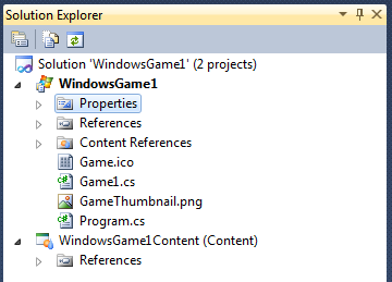
The Project Properties item, shown in the Solution Explorer
Then, set the profile to ‘Reach’:
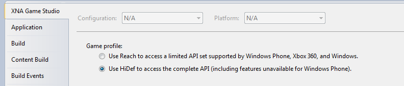
The Project Properties Panel
The reason for this is that you don’t need all the whizbang features of the XNA Hidef profile (trust me - you’re just visualising some data), and your code may not run without doing this. I certainly had trouble on my laptop graphics card.
2: Find a model from the Internet, and import it
In 3D Graphics programming, Models are the 3D objects that we pull in to our 3D world. They simplify drawing 3D objects immensely, and especially in XNA. Because we’re building a device that monitors the hip joint, I picked the most awesome skeleton I’ve seen in a long time (added bonus - released to public domain). I then used the instructions in this MSDN tutorial to import and draw the model on screen. By the way, the skeleton was a blender file and we need an fbx file. Fortunately, blender, a great bit of 3D modelling freeware, can handle the export for us.
Also, when you add the model to your Visual Studio Solution, make sure you add it to the ‘Content’ part, as shown below:
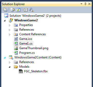
The Content Section in the Solution Explorer
And lastly, on the line that actually loads the model, make sure the file extension isn’t present. Mine looks like this:
myModel = Content.Load("Models\\FGC_Skeleton");After fiddling with those minor details, it’s time to run the program:
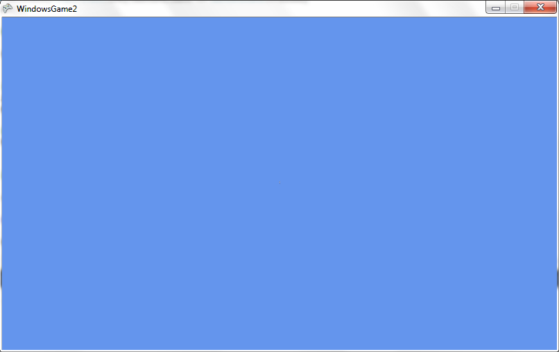
…uh, wait a second… what’s going on here?
Closer inspection of the code reveals that we’ve currently got our camera set a long way away:
// Set the position of the camera in world
// space, for our view matrix.
Vector3 cameraPosition = new Vector3(0.0f, 50.0f, 5000.0f);
This was fine for the default model that the tutorial was using - but they were drawing a spaceship, and we’re showing a skeleton. The camera here is targeted at (0,0,0), and so if it’s currently located at (0,50,5000), it’s a heck of a long way away. Try changing it to something a little more reasonable:
// Set the position of the camera in world
// space, for our view matrix.
Vector3 cameraPosition = new Vector3(0.0f, 50.0f, 50.0f);
And then run your program again. You should see something like this:
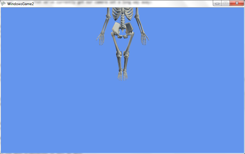
And voila! We’ve finally got a skeleton on the screen, albeit part of it. I’ll leave it to you to figure how to get the whole skeleton on screen, but as a hint: keep playing with the cameraPosition variable, and try changing the Vector3.Zero in the code below.
effect.View = Matrix.CreateLookAt(cameraPosition,
    Vector3.Zero, Vector3.Up);
3: Rotate!
We get a great tip on how to do this from the XNA tutorial mentioned above - take a look at the code provided in the Draw() method shown in the article:
// Draw the model.
// A model can have multiple meshes, so loop.
foreach (ModelMesh mesh in myModel.Meshes)
{
    // This is where the mesh orientation is set, as well
    // as our camera and projection.
    foreach (BasicEffect effect in mesh.Effects)
    {
        effect.EnableDefaultLighting();
        effect.World = transforms[mesh.ParentBone.Index] *
            Matrix.CreateRotationY(modelRotation)
            * Matrix.CreateTranslation(modelPosition);
        effect.View = Matrix.CreateLookAt(cameraPosition,
            Vector3.Zero, Vector3.Up);
        effect.Projection =
            Matrix.CreatePerspectiveFieldOfView(
                MathHelper.ToRadians(45.0f),
                aspectRatio, 1.0f, 10000.0f
            );
        }
        // Draw the mesh, using the effects set above.
        mesh.Draw();
    }
}
See the mention there to mesh.ParentBone? Bones define the part of the model that the mesh sticks to. If it helps, you can think of the mesh as the skin - the thing you see - and the bone as the invisible thing underneath that defines where the skin moves.
So, then, all we need to do is add another transform telling the left leg bone to rotate, right?
First, we have to find the right leg bone. I opened the model again in blender, and found our answer on the right hand side of the window:
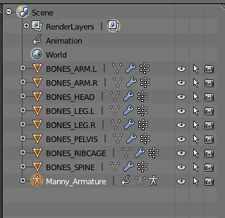
The model’s bones, in Blender
Wow, that was easy! The bone’s just called BONES_LEG.L. It might not be called the same thing in XNA, however, and we can check that by adding a line to the XNA code. Take a look at the code sample below, and then i’ll explain what I’ve done:
protected override void Draw(GameTime gameTime)
{
    GraphicsDevice.Clear(Color.CornflowerBlue);

    // TODO: Add your drawing code here
    Matrix[] transforms = new Matrix[skeleton.Bones.Count()];
    skeleton.CopyAbsoluteBoneTransformsTo(transforms);
    foreach (ModelMesh mesh in skeleton.Meshes)
    {
        foreach (BasicEffect effect in mesh.Effects)
        {
            Debug.WriteLine(mesh.ParentBone.Name);
            Matrix rotateAdjust = Matrix.Identity;
            turnout = 10;
            elevation = 45;
            if (mesh.ParentBone.Name == "BONES_LEG_L")
            {
                rotateAdjust = Matrix.CreateRotationZ(
                    MathHelper.ToRadians(turnout));
                rotateAdjust *= Matrix.CreateRotationX(
                    MathHelper.ToRadians(elevation));
            }
            effect.EnableDefaultLighting();
            effect.World = rotateAdjust *
                transforms[mesh.ParentBone.Index];
            effect.View = Matrix.CreateLookAt(
                cameraPosition, cameraTarget, Vector3.Up);
            effect.Projection =
                Matrix.CreatePerspectiveFieldOfView(
                MathHelper.ToRadians(45.0f),
                aspectRatio, 1.0f, 10000.0f);
        }
        mesh.Draw();
    }

    base.Draw(gameTime);
}
Oh, by the way - I changed the variable MyModel to skeleton. Just to keep things so that they made more sense :)
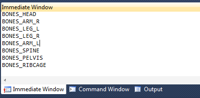
Ok! The first thing we did there was add a snippet of code that prints the name of every bone. This allows us to verify the name of the bone in XNA, and, as we can see - the name of the bone isn’t BONES_LEG.L, but BONES_LEG_L. You can find the output in the Immediate Window of Visual Studio - though you might need to pause program execution in order to read it properly!
The second thing is that we added another two variables here: turnout and elevation. These are the values I’ll be reading from the serial port - the first one specifies how far the leg is turning out (the opposite of pidgeon-toeing), and the second specifies the angle the leg makes with the vertical axis of the body. For the time being, however, we’ll just set them to arbitrary values - 10 and 45 - so we can test the rendering without worrying about having a serial port device hooked up.
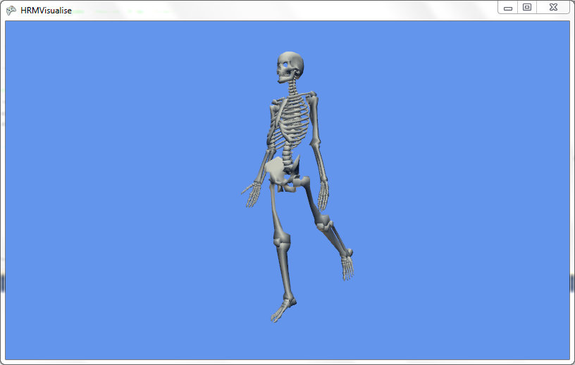
Alright! Let’s take a look:
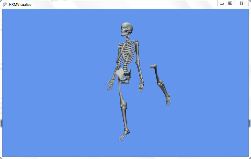
Oh dear! There’s something seriously weird going on here… it appears as if the skeleton’s leg is floating! What’s going on actually is that the leg is rotating around the skull. You can kind of see this by drawing a straight line along the axis of the leg and watching where it intercepts the skeleton.
4: Adjusting the model
We can fix this by opening up blender again with the skeleton model. I’m not going to go into all the details of how to use blender here - it’s pretty complex - but basically, the idea is to move the origin of the bone down to where it actually belongs - at the hip joint. Completed, it looks like this:
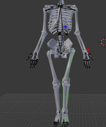
The difference is, that yellow dot has now moved from the head of the skeleton to the hip, and that is what the leg rotates around in our code.
Great! We can now re-export, load the model and we’re ready to go.
Hooray!
Review
To recap, here’s what we covered today:
- Serial port buffering and data management
- Finding, modifying and loading free models in XNA
- adjusting parts of models based on current serial port data.
Magic! I hope you find some of this useful in your own projects in the future.