Well, I’m doing a project at Uni at the moment in a team of eight. Don’t get me started about the coordination nightmare!
We’re building a Hip Replacement Monitor: the idea being as follows:
- When someone gets hip replacement surgery, there’s a large risk of the hip joint dislocating
- Patients need to know which movements will and will not contribute to this risk
- The hip replacement monitor sounds an alarm when the hip moves beyond its limits, and periodically (a few times a second) logs data to an SD card, so that the rehabilitation specialist can analyse the data and identify any issues the patient may be having.
The concept seems to be fairly sound (I mean, it’s got a couple of issues, like the fact that the buzzer is going to get mighty annoying), but we’ve been having major issues implementing the system over the last little while.
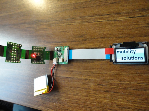
After burning out two Seeeduino FILMs and buying a couple of Sparkfun LSM303DLH breakouts only to find out that we’d need level shifters in order to use them with our I2C bus we finally got a very basic system working today with a friend’s Arduino Nano 3.0 and a Pololu LSM303DLH breakoutworking. You can take a look at a demo video here.
Because I had such a hard time figuring out what was going on, I figured I’d document part of the process I’d gone through, so that others can learn from our mistakes.
Lesson 1: Check your voltage levels before you buy.
So turns out that the LSM303DLH chip’s I2C lines run at 1.8V, despite it being supplied on between 2.5 and 3.3V. Whilst this would work on a 3.3V microcontroller, which will read anything above 1.65V as high, changing to a higher voltage micro would cause problems. Furthermore, any effects of line impedance would be heightened by the lack of leeway between the threshold voltages, and the 3.3V outputs from the microcontroller could have the effect of overloading the sensor.
For these reasons, we ended up buying another set of LSM303DLH breakouts, this time from Pololu - these had level shifters built in.
Lesson 2: Double check the Arduino pinouts before connecting anything.
The Official Arduino Nano Page clearly states that the I2C bus pins are “pin 4 (SDA) and pin 5 (SCL)”. Ok, fair enough - referencing the photo, these should be labelled D4 and D5, right?
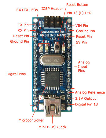
Ambiguous!
Nope! Actually, we’re looking for A4 and A5! Having worked with AVR chips before, I found the answer here, but, at time of writing I realised that this information was also available on the Pololu github page. I should probably mention that I figured out that D4 and D5 weren’t right by connecting the two pins to an oscilloscope, which brings us to the next lesson…
Lesson 3: Check hardware if checking the software doesn’t give you much help.
This may seem blindingly obvious, but, as an electrical engineering student who’s had to do extremely little practical work up til now, it was very easy to forget.
Our team spent ages debugging the LSM303DLH library provided by Pololu before a carefully placed Serial.println() informed us that there was no data available to be read from our I2C peripheral. We then connected an oscilloscope up to the SCL and SDA pins on our Microcontroller, only to obtain no signals (+3.3V constantly).
We then decided to reconnect an I2C OLED screen that connects straight up to the FILM and had worked previously for us out of the box to check if the I2C circuitry was working… alas, nothing. Here’s a before and after:

Before / Trololololol...
…Ok, whilst the screen didn’t look quite like that, it did look pretty close to nothing. Time to give up on the FILM and try a different micro.
Lesson 4: A little bit of soldering goes a long way towards avoiding hardware problems.
We found that whilst the LSM303DLH stuck to the breadboard with the supplied pins (nifty!), we couldn’t guarantee the electrical connectivity between the two. So, I soldered the pins onto the chip, which obviously fixed the problem and made the whole thing a lot easier to prototype.
Lesson 5: Don’t solder at the table whilst your wife is trying to write a comparative law essay nearby.
She may get a headache, and/or start singing strange songs. (listen carefully in this video)